
12
2020/05
Installation and Commissioning Methods for Screw Conveyors
The foundation for the screw conveyor shall be fully cured and compacted 20 days prior to the equipment’s formal installation, ensuring a solid and reliable base that prevents settlement or deformation of the conveyor and maintains adequate stability during operation.
1. The foundation for the screw conveyor shall be fully cured and compacted 20 days prior to the conveyor’s formal installation, ensuring a solid and reliable base that prevents settlement or deformation and maintains adequate stability during operation.
2. The assembly of the enclosure shall comply with the following provisions:
⑴ The permissible deviation for longitudinal straightness is 1/1000 of the length, and the permissible deviation for overall straightness is 3 mm.
(2) The lateral straightness tolerance is 1/5000 of the width.
(3) The clearances on both sides between the inner wall of the casing and the screw shall be equal, with an allowable tolerance of 2 mm; the bottom clearance shall have an allowable tolerance of ±2 mm.
(4) The joints of the enclosure shall be tightly fitted with no gaps.
⑸ The casing shall be securely padded against the frame.
3. The permissible deviation in alignment between the shaft or bearing centerline and the longitudinal centerline of the screw conveyor is 0.5 mm.
4. The inner surfaces of adjacent casings shall not exhibit any significant misalignment at their joints.
5. After all sections of the screw conveyor have been fully and securely adjusted, proceed to tighten the foundation anchor bolts.
6. The low-speed shaft of the drive unit and the front shaft of the screw conveyor shall be aligned on a common axis. When a flexible coupling is used, the parallelism deviation shall not exceed 1/100, and the misalignment shall not exceed 0.2 mm; when a rigid coupling is used, the angular error between the two shaft axes shall not exceed 1°30′.
7. If the inlet and outlet openings are to be installed on site, they shall be welded only after the entire machine has been securely fixed. The flange bearing surfaces of the inlet and outlet openings shall be parallel to the screw conveyor’s axis, and their joints with the hopper shall fit tightly without any gaps.
Adjustment of the screw conveyor:
1. All suspension bearings of the screw conveyor shall reliably support the connecting shaft, ensuring that the screw is neither jammed nor bent under load. During installation, the number of shims for the suspension bearings must be adjusted so that no gaps are formed between the bearing split surfaces, while an appropriate radial clearance is maintained between the bearing and the connecting shaft.
2. The suspension bearing shall be installed at the midpoint of the connecting shaft, with end-face clearances of greater than 10 mm from each helical tube shaft end (when the helical diameter D ≤ 400 mm) and greater than 20 mm from each helical tube shaft end (when the helical diameter D ≥ 500 mm).
3. To compensate for cumulative length errors between the casing sections and the screw, it is permissible during installation to place woven asbestos strips between the flanges of each casing section. Whether to install a waterproof canvas gasket between the casing and the cover shall be determined based on the sealing requirements.
4. When the center height of the low-speed shaft of the drive unit’s reducer differs excessively from the center height of the screw conveyor, shims may be used to adjust the height of the drive unit.
5. During no-load trial operation, if oil leakage is observed from the bearing, the bearing shall be removed and the tension of the spring in the sealing ring adjusted until the leakage ceases.
6. During no-load trial operation, if the temperature rise of the suspension bearings is excessive (during no-load trial operation, the temperature rise of each bearing shall not exceed 20°C; during loaded trial operation, the temperature rise of each bearing shall not exceed 30°C), this indicates that the suspension bearings are improperly positioned, resulting in jamming of the connecting shaft. In such cases, loosen the set screws and adjust the position of the suspension bearings.

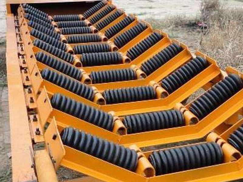
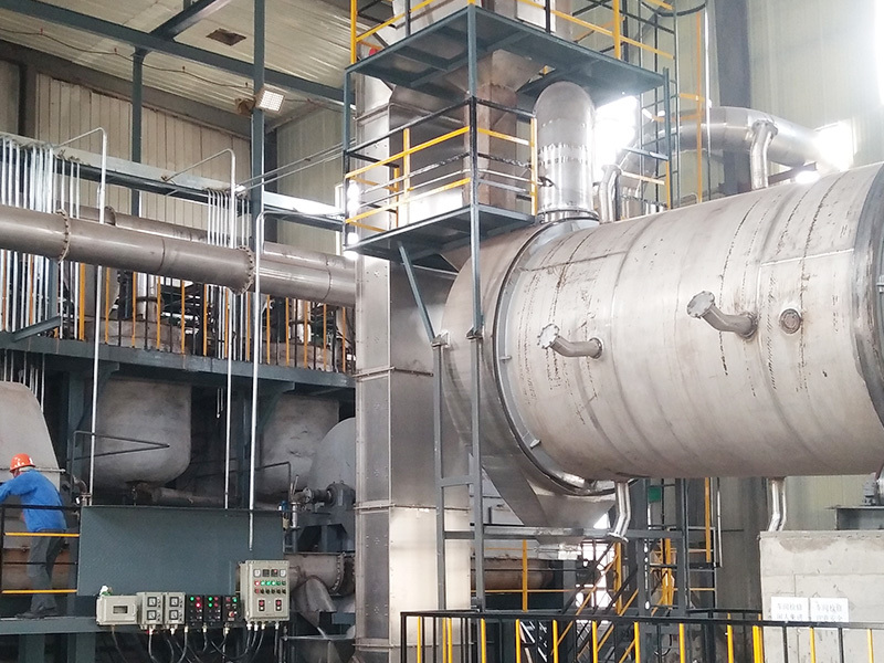
Specializing in the manufacture of elevators for over 20 years.
Hengshui Changhong Mining Machinery Co., Ltd. has been specializing in the manufacture of hoists for over 20 years, integrating technological development, production and operation, and technical services into one. Drafting author of Changhong Z-type (vertical spiral bucket) elevator enterprise standards, patent-technologied manufacturer, reputable producer of mining machinery with superior quality and strength.
Contact Info
Contact: Manager Pang
Phone:8613932836877,8613315840327
Phone:0086-318-4869777
Fax:0086-318-4868277
Email:384023722@qq.com
Address: Mada Development Zone, Fucheng County, Hengshui City, Hebei Province


